
Independence day and summer airplane building with friends
Happy Independence Day readers!!! It’s been a little while (almost 3 months) since we wrote last time, but rest assured, we have been hard at work. In this blog post, we describe our latest progress, as well as our plans for avionics and upholstery.
Short summary of things we did since the last build:
- Installed front part of the floor
- Installed rudder pedals
- Installed elevator pushrods and torque tubes, aileron pushrods, autopilot pushrods, and flap torque tubes (and swap eyebolts a few times)
- Built front wheel assembly
- Cut one door window, and attempted to cut the other (Peter broke it in process, so now we wait on the replacement)
- Routed brake lines
- Added door latches
- Made a secondary comm antenna bracket and reinforcing channels
- Made front wheel fairing and start on main wheel fairings
- Started building firewall
- Started planning upholstery and avionics
Read on for details :)
Front floor
One of the first things we did since the last blog post was adding the center fuselage floor, and control sticks housings. We were building the floor on a flat (horizontal) surface (composed of 2x4s on top of dewalt easels).
When installing joysticks, however, we found a few things that did not quite match. For instance, below the joystick looks a tiny bit too short for the housing:
Claude found the reason - the front floor is supposed to be somewhat raised. This is probably not an issue builders raise often, because, according to the manual, all the control pushrods are supposed to be installed when the side-skins are on (and the side-skins would determine the angle of the floor). However, we realised it is much easier to install pushrods (as well as fuel lines, wiring etc) without the side skins, which is why we are holding off on installing side skins for the moment.
Rudder pedals
Installation of rudder pedals was reasonably straightforward, except the order of riveting needs to be thought a bit ahead (it’s easy to rivet the wrong thing first and block access to other rivets). We sourced the help of our friends (and Sasha’s colleagues – pictured here Andrew in the middle of riveting) in the process:
Elevator, aileron, autopilot pushrods, flap torque tubes
This part was actually somewhat tricky. Controversial points upfront – our torque tubes seem to be moving smoothly out of the box :) A lot of builders (including Claude) report that the flap and elevator torque tubes require a lot of tuning / grinding, while ours seem to move smoothly out of the box. It may be a stroke of mad luck, however, we suspect, there is another reason – we installed 4 bushings for flap torque tube, and 2 bushings in the aileron torque tube in such a way that there is only one bushing per rib (basically, bushings at the top and bottom tubes are staggered). That way, no single rib is forced to bend and accommodate both torque tubes (which may cause binding).
Another point to attract builder’s attention to is the service bulletin by Sling Factory about replacing thin-necked eyebolts with thicker eyebolts. Good factory eyebolts are the lubricated kind (with a tiny lubrication port); as those eyebolts are in hard-to-access places, we are replacing them with teflon (PTFE)-insert lubrication-free eyebolts. There are two kinds of those eyebolts available on mcmaster-carr – highly corrosion resistant and high strength ones. High strength ones are about 7 times stronger than corrosion resistant ones, and, after reading the Factory service bulletin, we decided to go with high strength. Naturally, that happened after we ordered and installed corrosion resistant eyebolts first, and had to re-order and reinstall them. For future builders, the eyebolts are about ~ $ 20 apiece, so order the correct ones the first time :) – it will spare you money, and a lot of time (those pushrod assemblies have very inconvenient access even with side skins off, and so installing them and taking them off takes a lot of time). Eyebolts are made of stainless steel, and the pushrods – of aluminum, so we are using corrosion inhibiter on the threads. Pictured below is Peter’s dad right before final (hopefully) assembly of the aileron pushrod.
Front wheel assembly
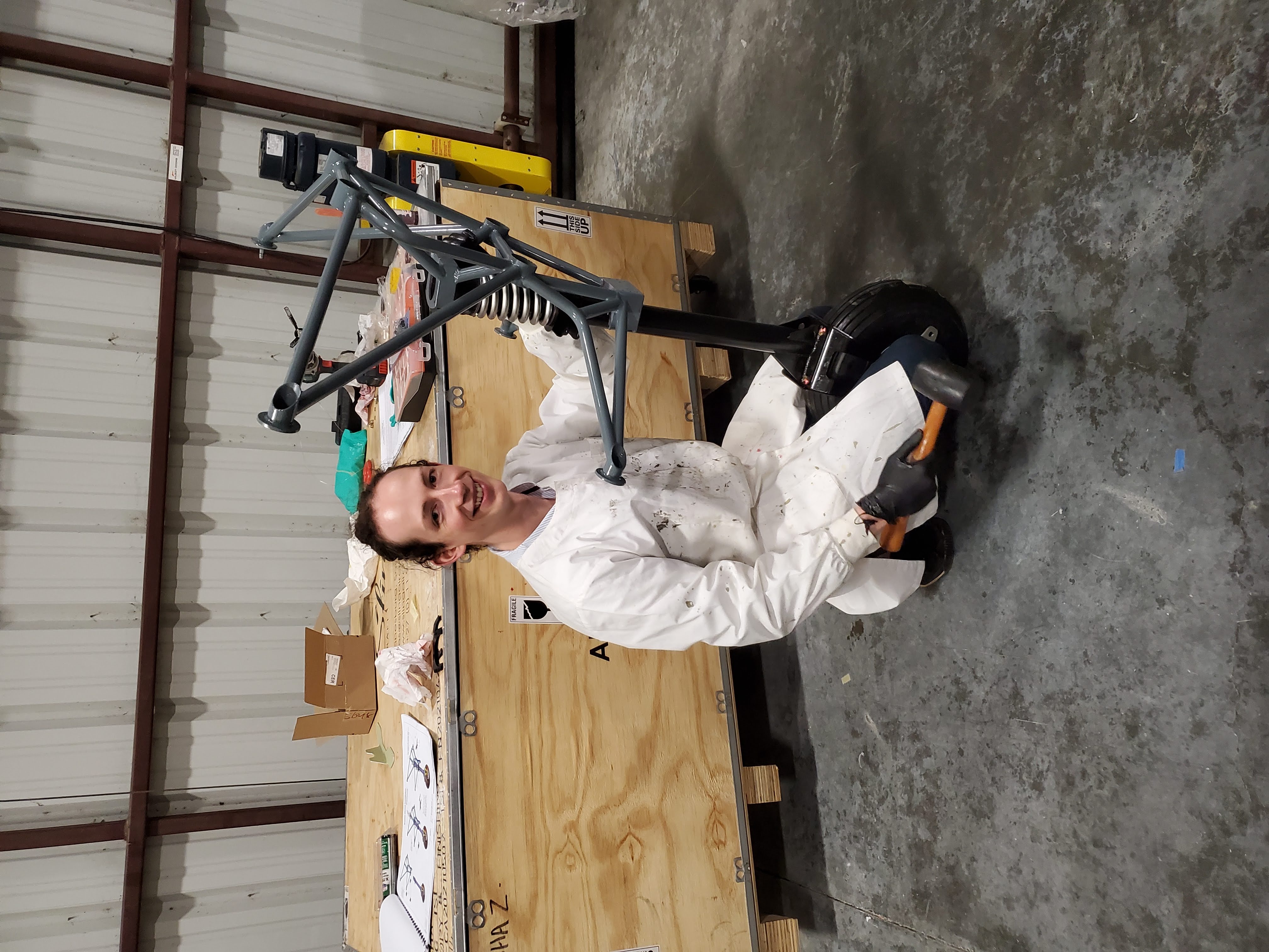
The instructions in the manual are reasonably straightforward here. Pictured below is Brandon with one of the early iterations of the assembly. Manual specifies “to apply ample lithium grease” to the bearings, so Brandon is wearing a lab coat to prevent being covered head to toe in lithium grease.
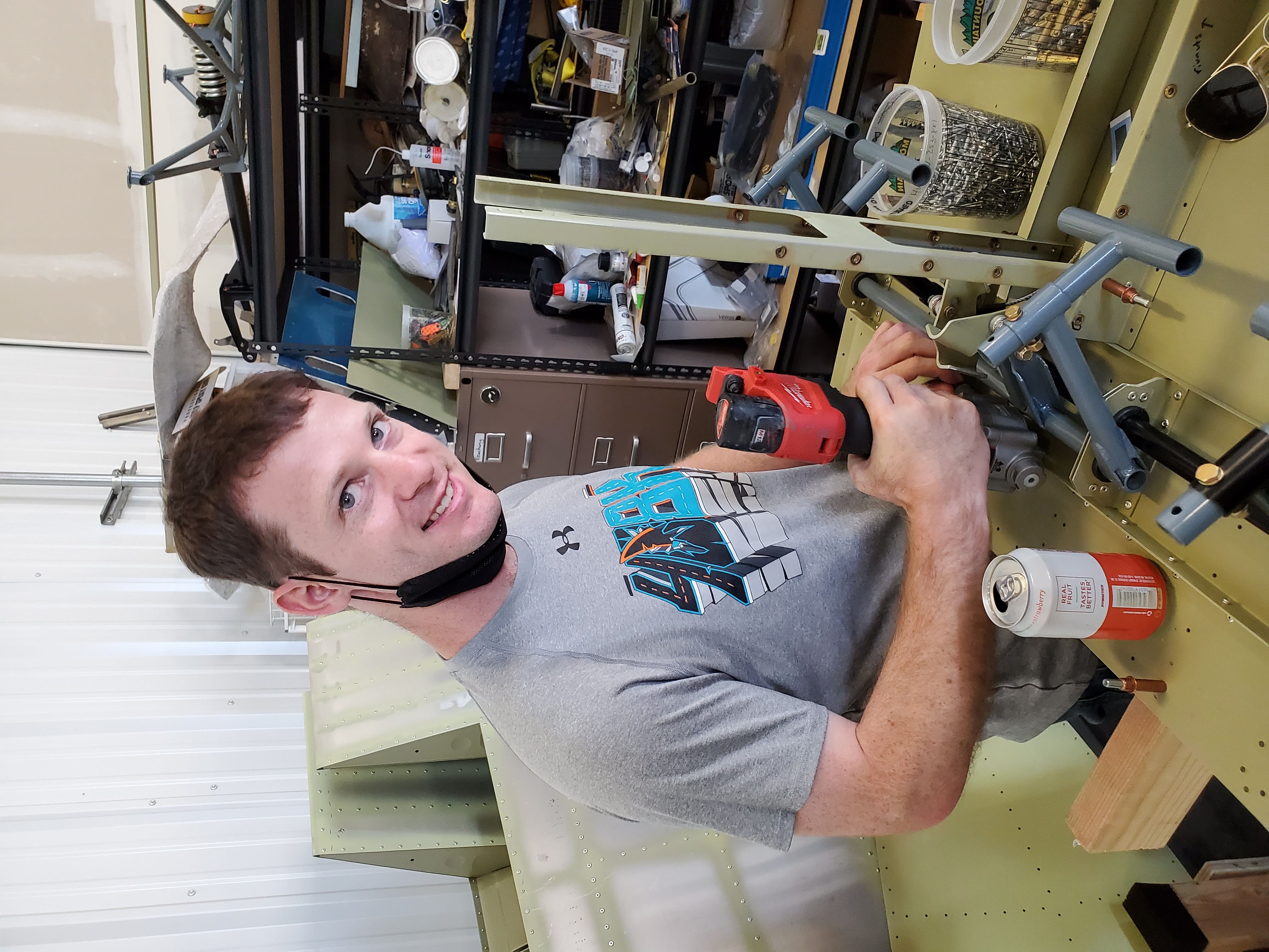
However, we second complaints of some builders that bushings that hold the front wheel fork are too tight and need to be opened a little bit. We used piston enlarging attachment for the hand drill + honing compound:
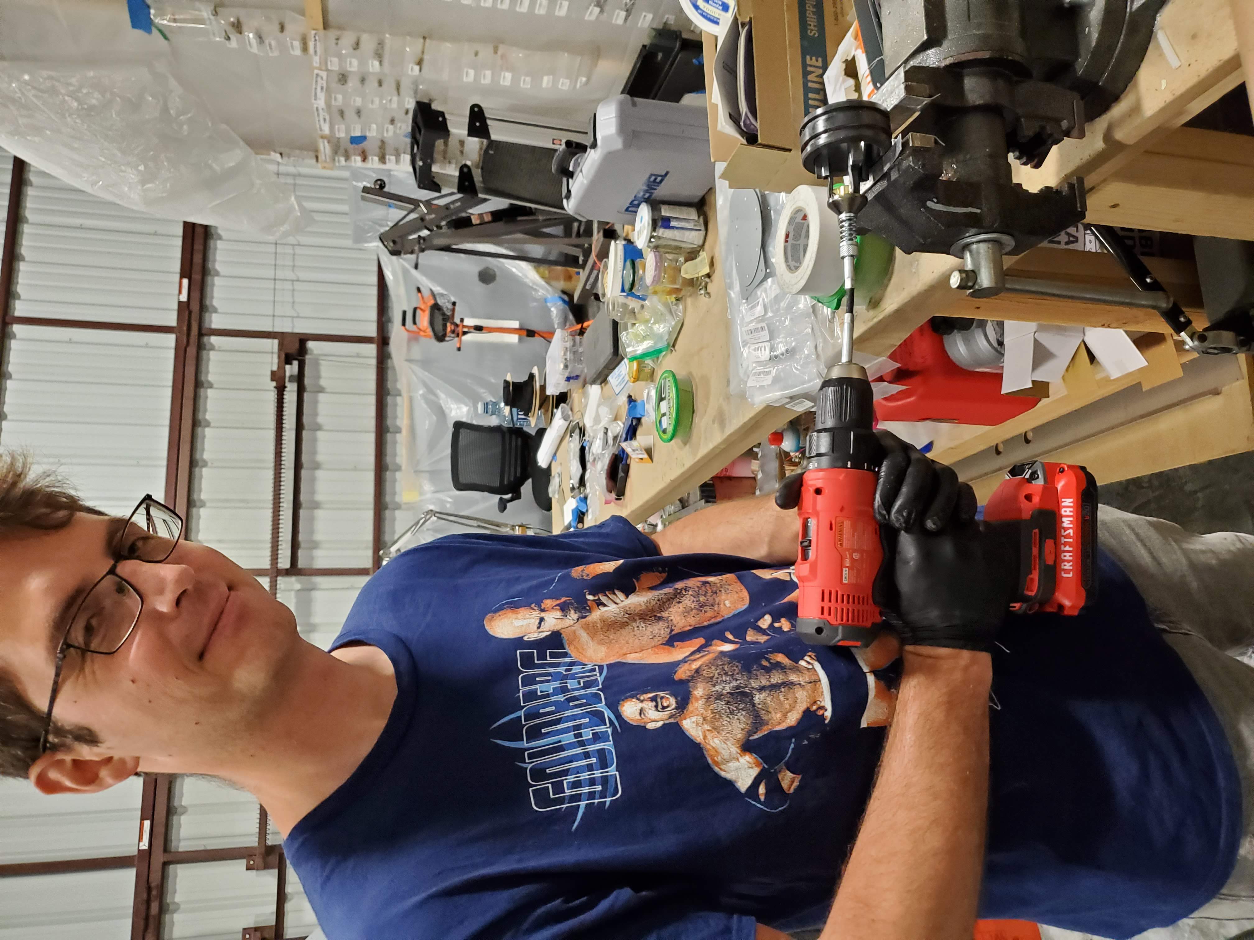
but even so, the process took a rather long time. We spend 4+ hours and several charges of hand drill battery grinding a little bit, putting things back together, grinding a little bit more etc), however, at the end of the process, one can reasonably easily turn the nosewheel by the pushrod horns by hand, so, hopefully, turning it via rudder pedals would be very smooth.
Doors and windows
At some point, we decided to take a break from the hangar, and go to Tahoe for a weekend. However, the work did not stop – we brought doors and window acrylic, and were working on door latches and cutting the windows.
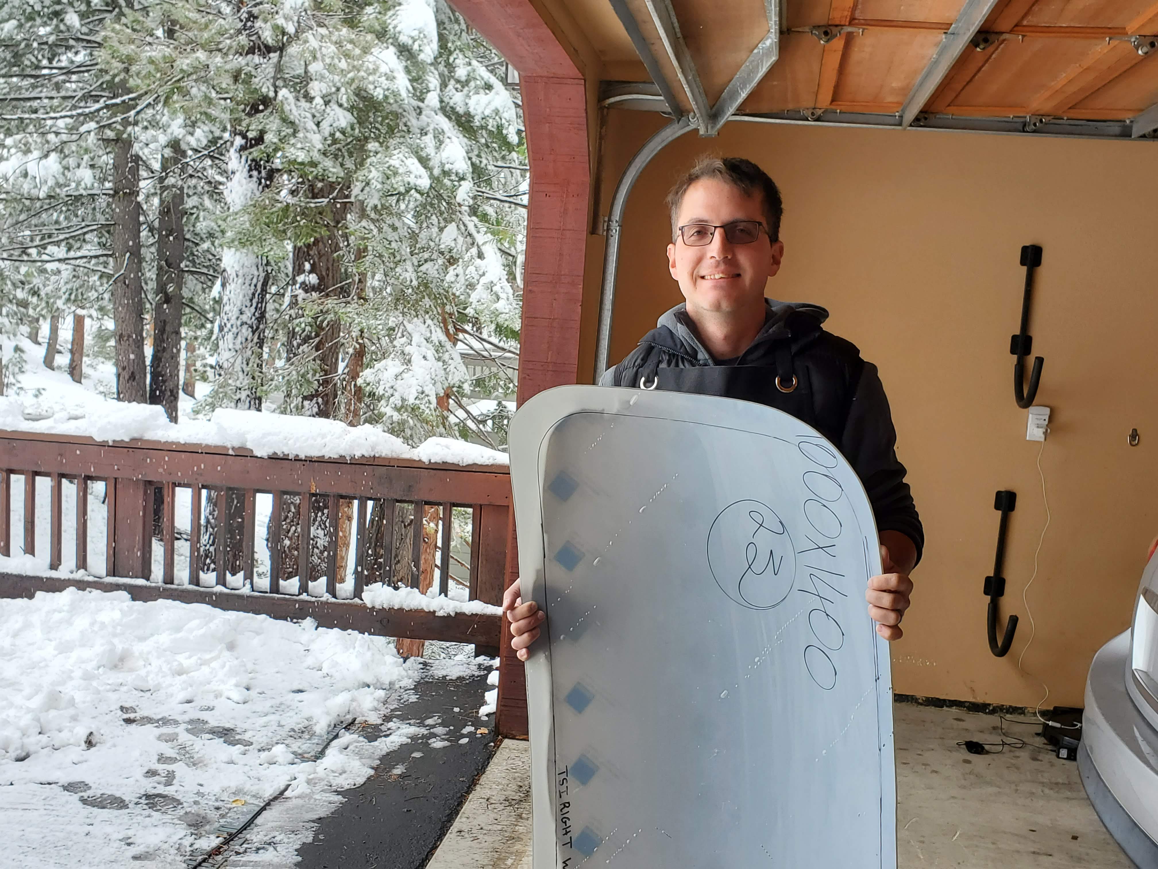
Evan (and Claude) sort of brushed the process of cutting windows under the rug, saying that one should cut the acrylic a little bit at a time. To us, that was not quite descriptive enough, so we tried to develop (and document) the procedure in more detail. We tried to film the procedure using the second window, however, we had an accident whereby Peter dropped the window and cracked it :( Now we are waiting on the replacement acrylic from the Factory.
Door latches – we f****** struggled. The part of the latch that is supposed to go onto the square shank was not sized correctly, so we had to file the latch hole to fit (note that the hole is square, so you cannot just drill / dremel it up). The other latch, on the other hand, was loose. There are several parts of the assembly in this situation - the bushing that the shank is supposed to rotate around had to be carefully dremelled up, the hole in the canopy that the whole assembly is supposed to drop into had to be dremeled up…you get the idea. There are a few rivnuts that are supposed to go into the canopy, but it’s not clear which rivnuts go where and if all of them are necessary/can even go into the canopy. More drilling! Side note – to secure rivnuts in fiberglass, we used jb weld instead of loctite, as, to our understanding, loctite does not work well with non-metals.
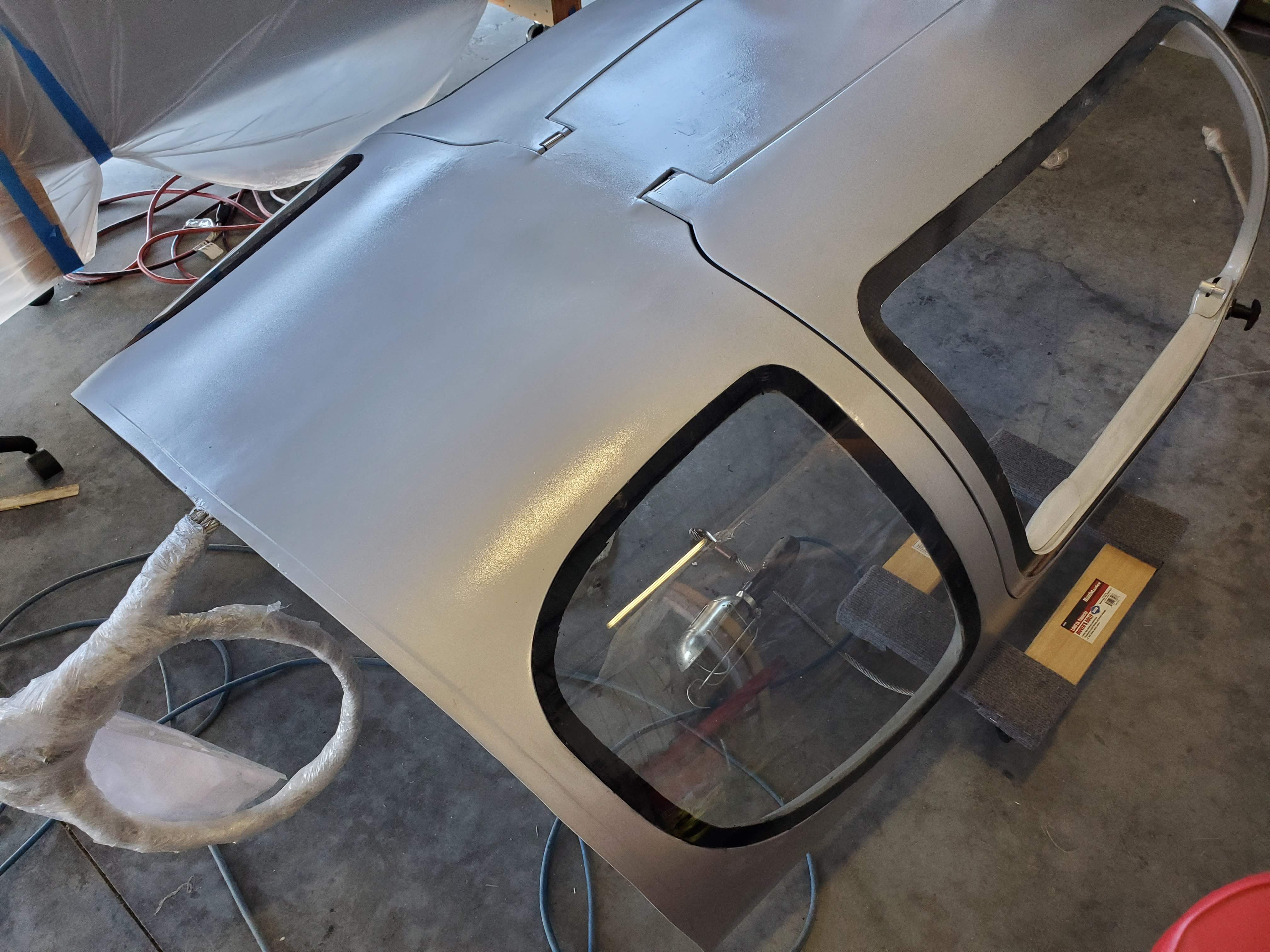
The instructions for door latches were also very vague on which bits go where. For instance, the clamp that secures the pushrod moving rear part of the latch seems to be present in some pages of the manual, but absent in the others. Also, it did not seem to fit (at least not with the fiberglass doors that we received). Our doors were also different thicknesses, neccessitating screws of different lengths to secure the latches. We were debating whether to add door windows before attaching the canopy to the fuselage (pictured below are Eugene debating, while Peter trying to route nylon brake lines through protecting hose – in hindsight, silicone lubricant would have made the latter job much easier),
but it is clear that the striker latch fitting will go a lot easier without the windows on. So, we decided to hold off on attaching the windows until we attached the canopy. This was another can of worms: figuring out which Sika primer was appropriate. The default Sika primer that Sling recommends is not sold in the U.S. However, there is a replacement Sika primer that is sold in the U.S. (on Mcmaster Carr no less!) that is advertised as a substitute for the Sling-recommended one. Here’s a compatibility table of sika primers, with the most relevant lines for us being PMMA (aka acrylic), aluminum, 2 component paint primer, and FRP (aka fiberglass) – note that for all of those, SP-207 is acceptable treatment in class 2 applications.
We worked all this out before we decided to hold off on attaching the windows until we’d attached the canopy. Hopefully some can profit from our earlier thoughtfulness :) Claude tried the MC primer in action and it seemed to stick fairly well.
Secondary Comm
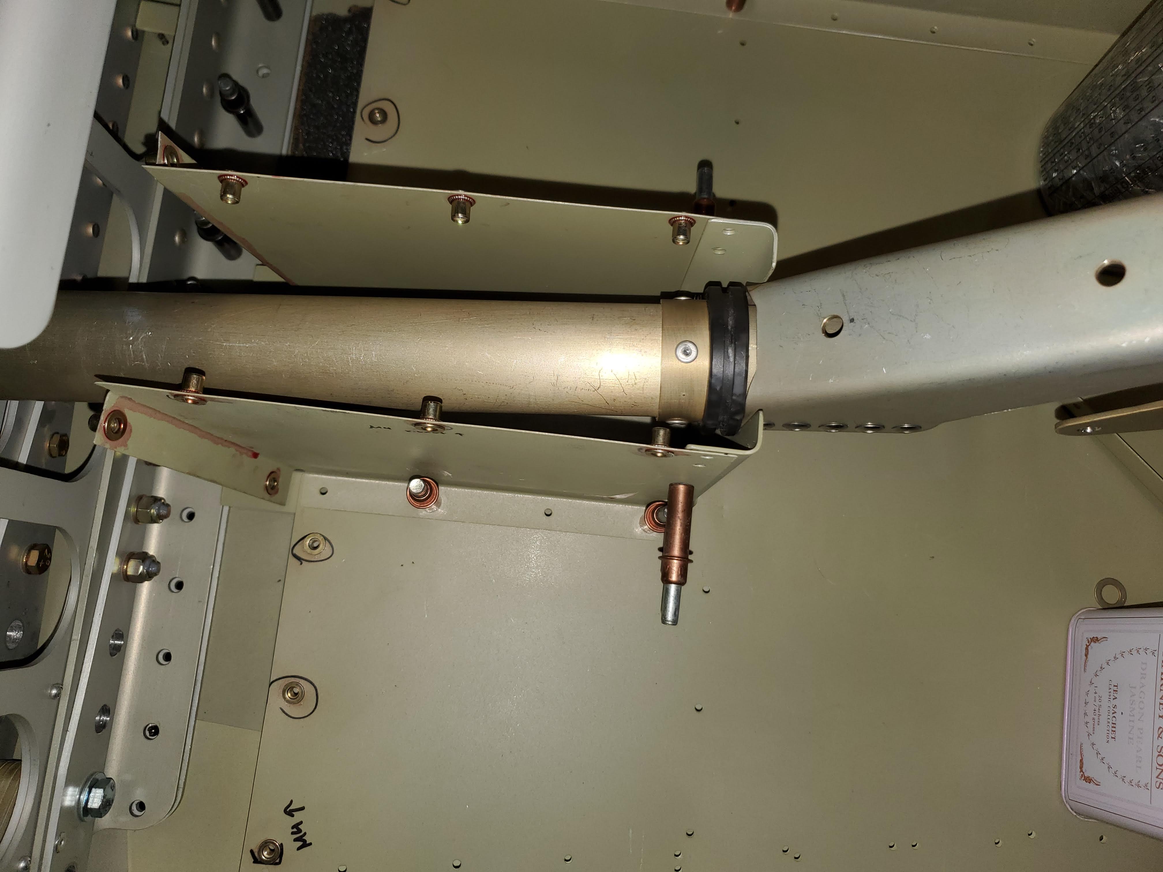
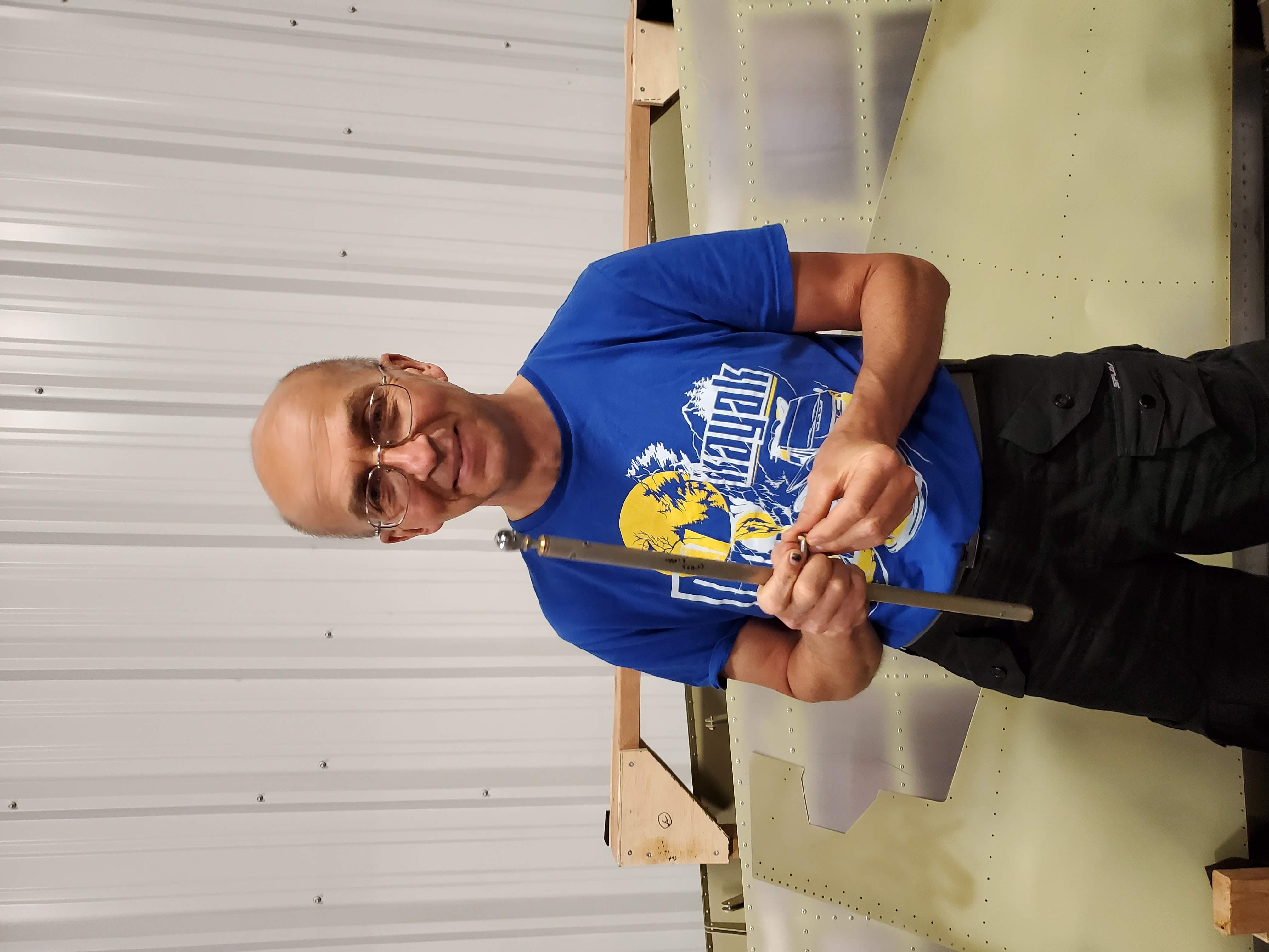
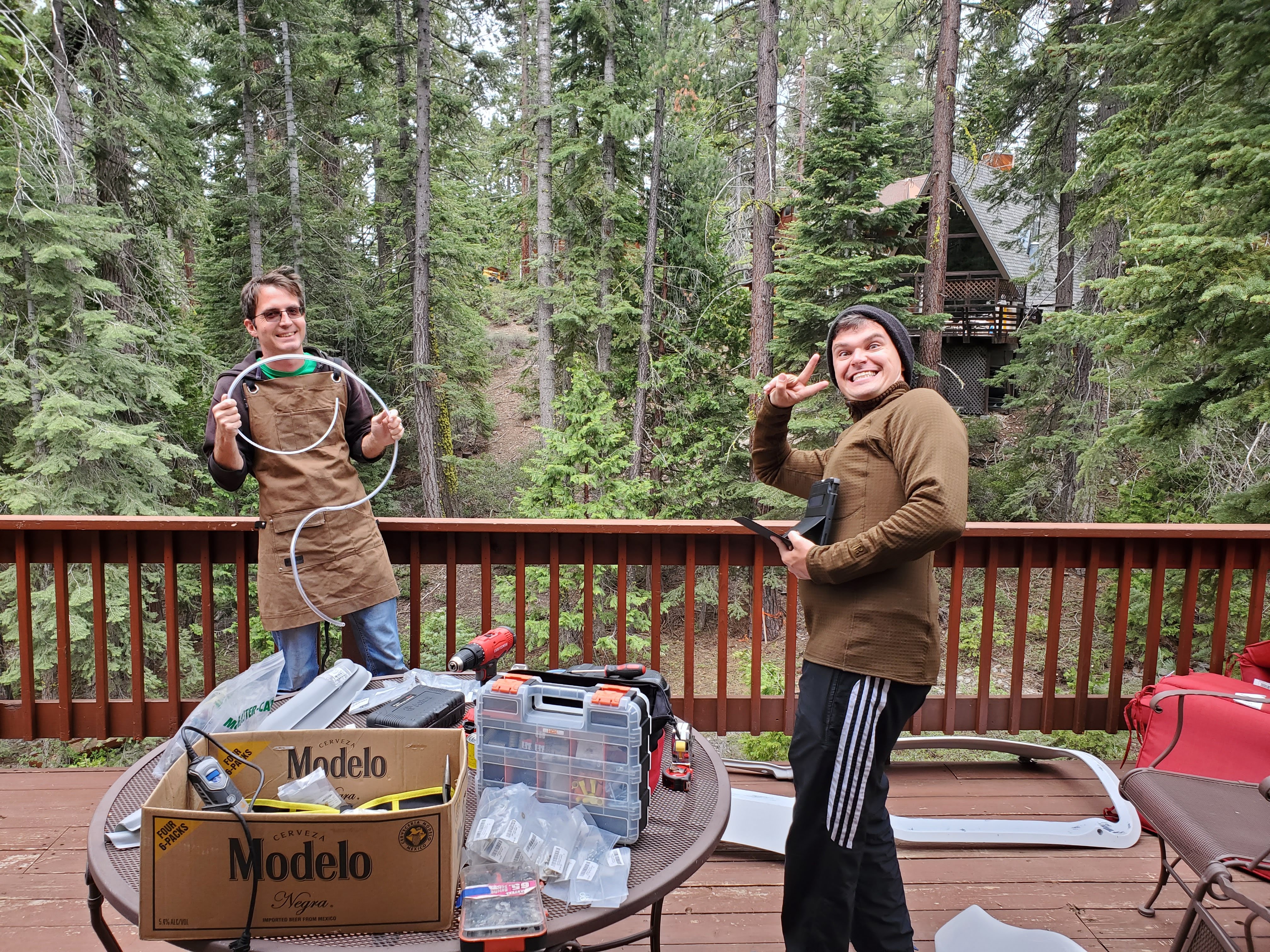
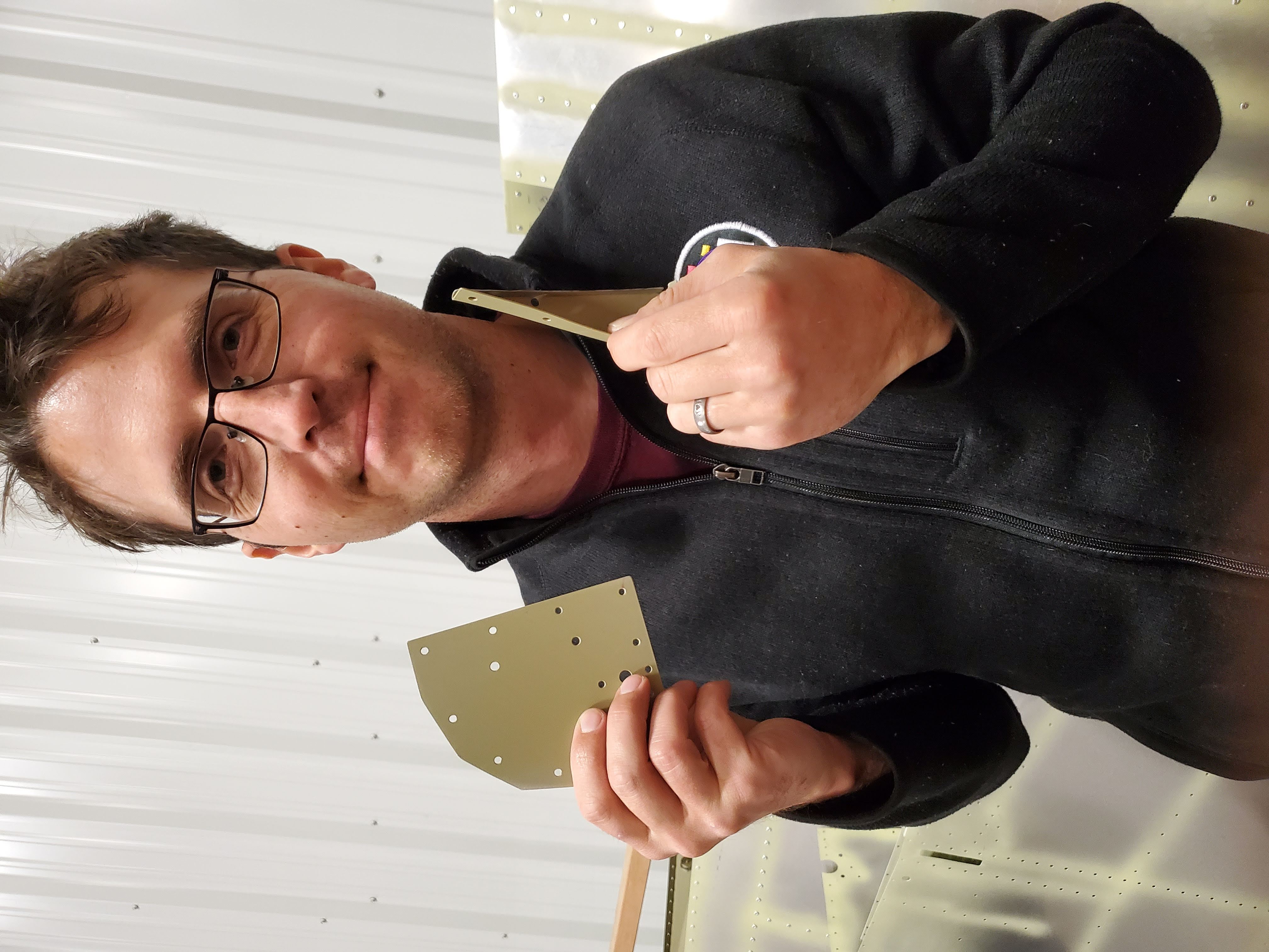
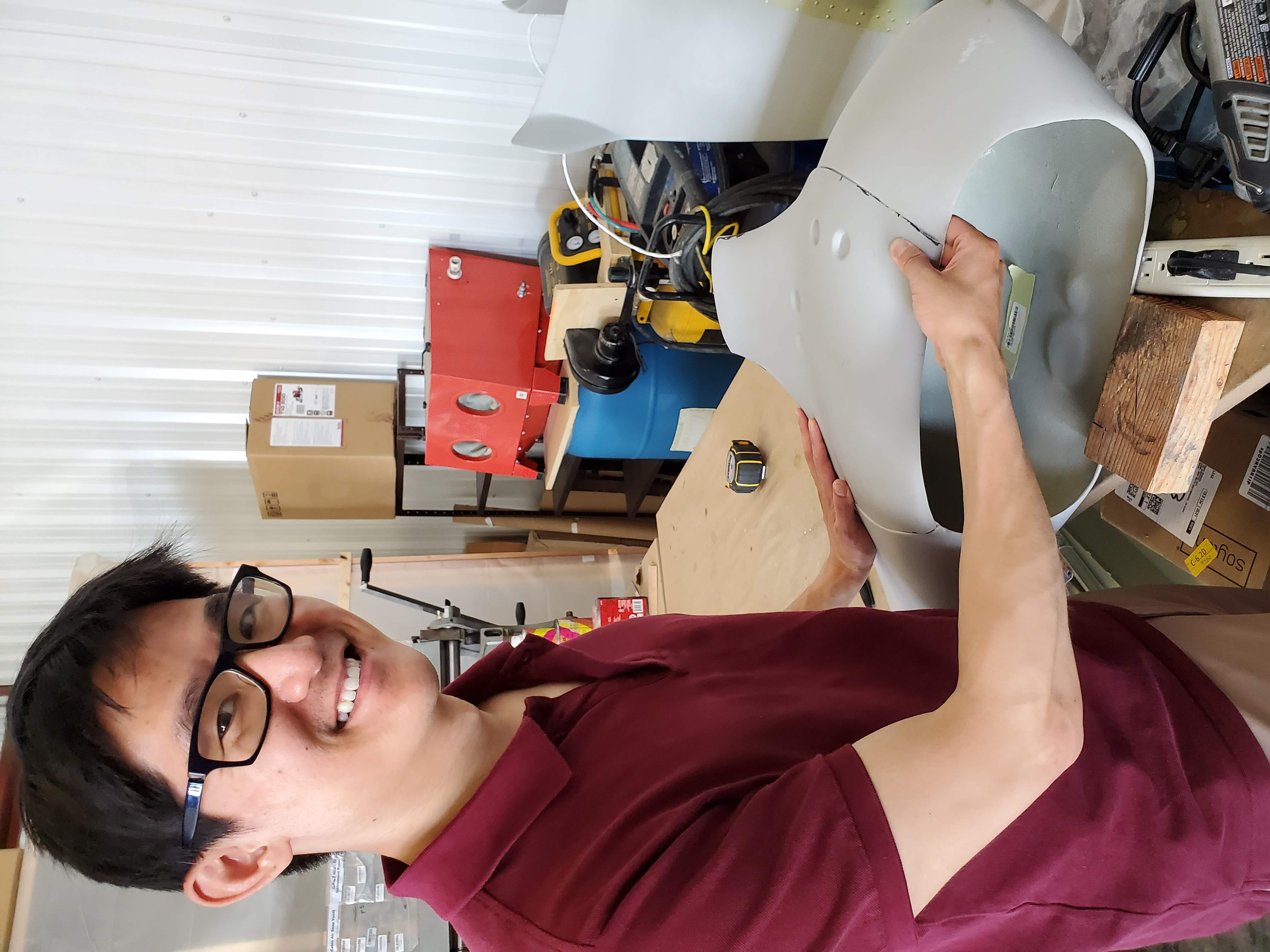
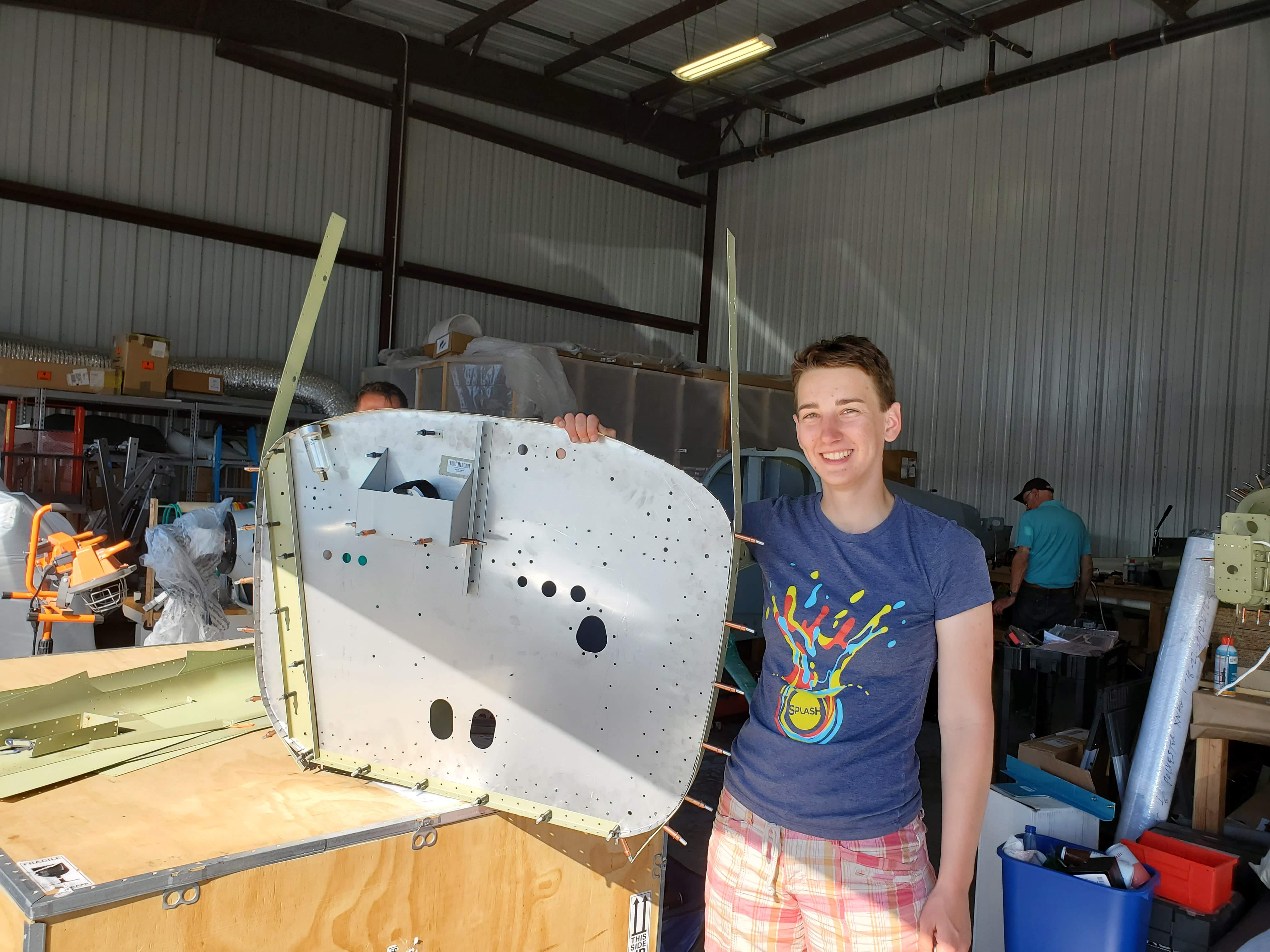
Thanks to Sasha’s IFR training, we know it is very important to have a backup NAV/COM receiver. A secondary radio receiver necessitates a secondary antenna. We followed Garmin recommendations and added the secondary antenna on the belly of the airplane, on the inspection panel already cut out on the previous location of the GMU 11 magnetometer. After discussion with Sling Technical, we found that this inspection panel is no longer useful for anything other than elevator pushrod bushing inspection and decided to repurpose it for our secondary antenna. However, this was not as as straightforward as it sounds; we added a stiffener channel as well as supporting brackets. We cut the channel from an extra longeron that we received in our kit, and bent the brackets from extra seat backrest doublers - here’s a picture of Peter holding doubler and bracket that we bent out of it:
This is how the final assembly looks like:
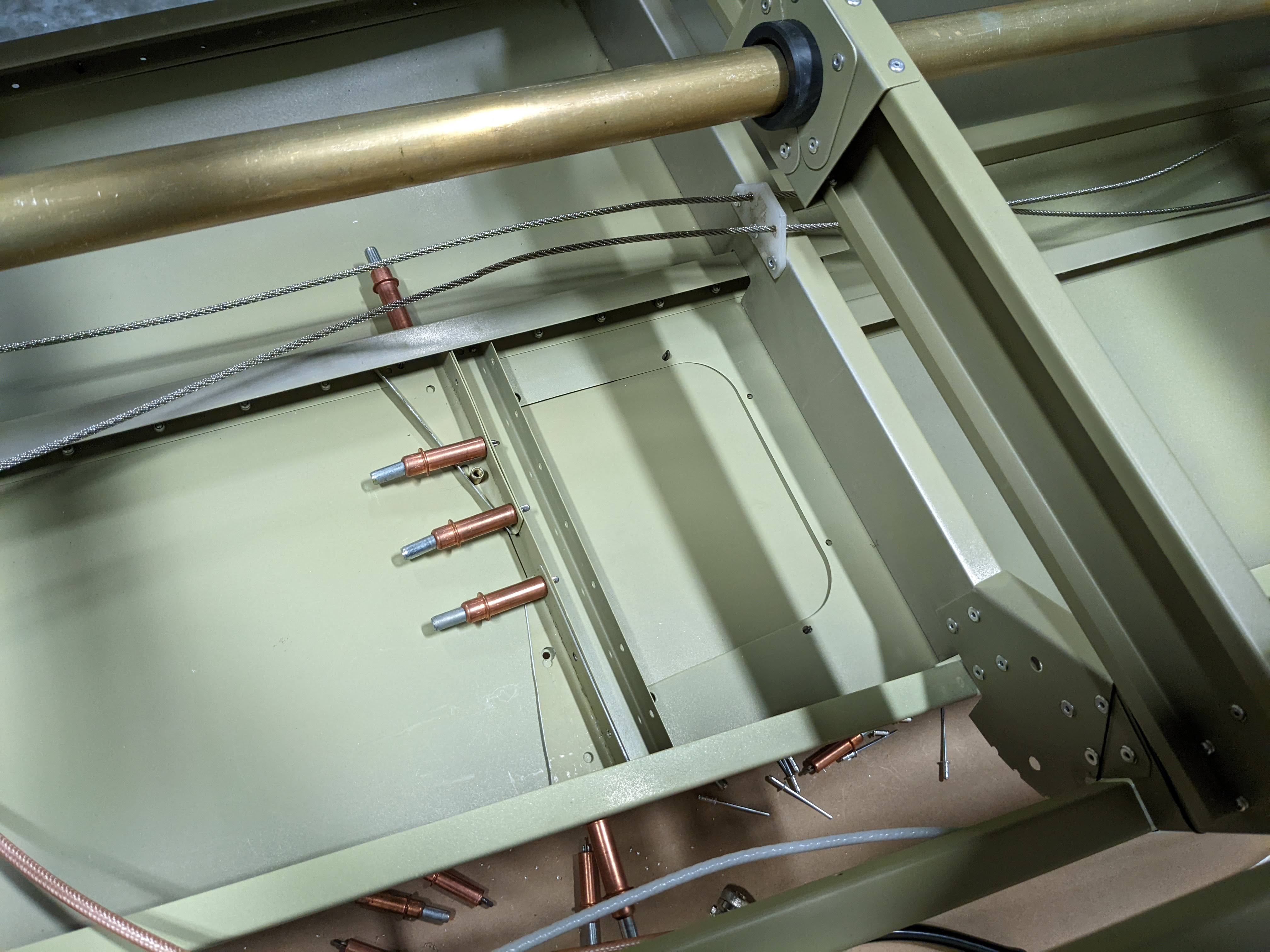
We added a RAMI AV-17 bent belly antenna specifically for this purpose and are hopeful that full lost comms will NOT HAPPEN on our airplane :)
One important thing to mention with regards to all antennas (aside from the GPS and VOR/ILS antennas) is that a ground plane is necessary. Since our whole airplane is primed, this requires special provisions such as scratching off the primer under the rivnut and skipping loctite to ensure electrical contact and good radio communication. We have to also ensure that the radio ground is connected to this ground plane as well (per our Airplane Wiring Workshop).
Wheel Fairings
In contrast to everything else, this bit is surprisingly straightforward so far. The only hiccup was that inner plates for main wheel fairings components came in two separate forms: one from the previous version of the fairing, and one from the current.
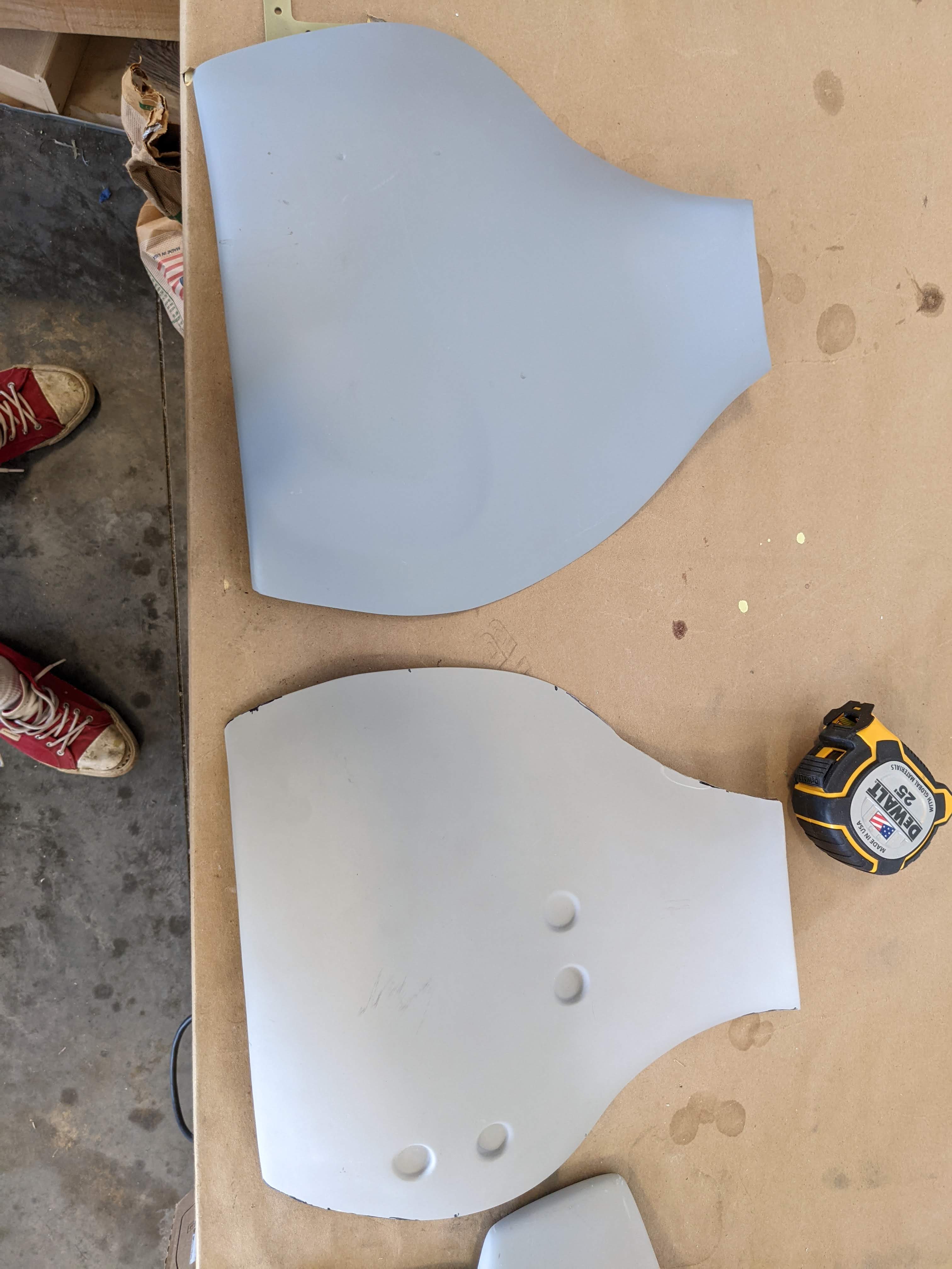
One of them (likely the previous version of the inner plate) does not fit with the current fairing:
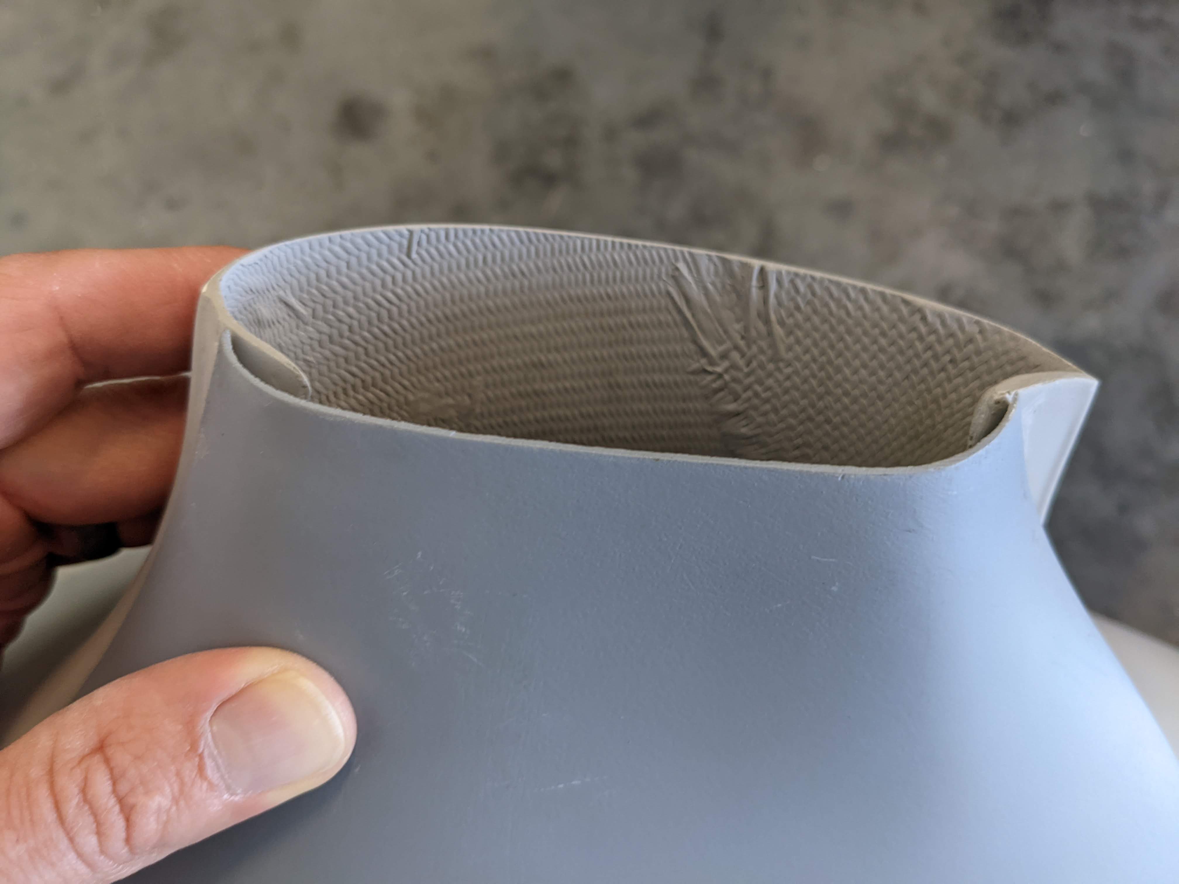
We ordered a new one so that we can have consistent wheel fairings. The one that fits, however, fits well, as Jonathan demonstrates:
Firewall
Placing components on the firewall is incredibly exciting! Especially once we remember that we started all the way at the rear of the airplane, and worked our way forward. With help of our friends (pictured below is Melinda proudly demostrating her work)
we have added battery holder, cowling strips, and reinforcement channels to the firewall. In the process, we also found a few components that we have not primed yet – neither of us could imagine we make it to firewall so soon, and so we did not prioritize priming FWF components in the previous priming sessions. There is only a handful of parts yet, so this also gave us an opportunity to try our new bonderite pen (aka alodine pen, aka cancer pen, as alodine liquids are known to be strongly carcinogenic). The manual outlines the following procedure for the pen:
- the part is scotch-brited and cleaned (strangely, the instructions recommends cleaning with water, we used acetone instead)
- the part is covered using the pen in one layer, thoroughly, but avoiding pooling
- first layer should dry
- within 5 minutes of first layer drying, second layer needs to be applied, using strokes 90 degrees from the strokes in the first layer
Having it done for one part, we realized it is likely a better option than priming for one or two parts, but will become too much hassle for more parts than that, so we’ll have another priming session for the remaining FWF aluminum.
Upholstery and avionics
We will provide a full report in future blogposts, but the short version is as follows - we have ordered avionics (full garmin g3x suite + vpx) from stein air, and have started planning the electrical and mounting system for it. Specifically, we are trying to figure out if we can fit into the electric envelope that single generator inside Rotax 915 (28A @ 14V) provides, and it looks like we can, but barely. We may need to replace the landing and taxi lights with less bright ones to ensure that when Pitot heat, lights, and autopilot servos are all on, current draw is below 80% of the max. Mounting-wise we are planning to copy what Midwest does and add a separate avionics shelf + inlet and output fans for cooling.
Thinking of upholstery, we decided that we want custom upholstery – both in terms of color (in our vision, it looks something like this):
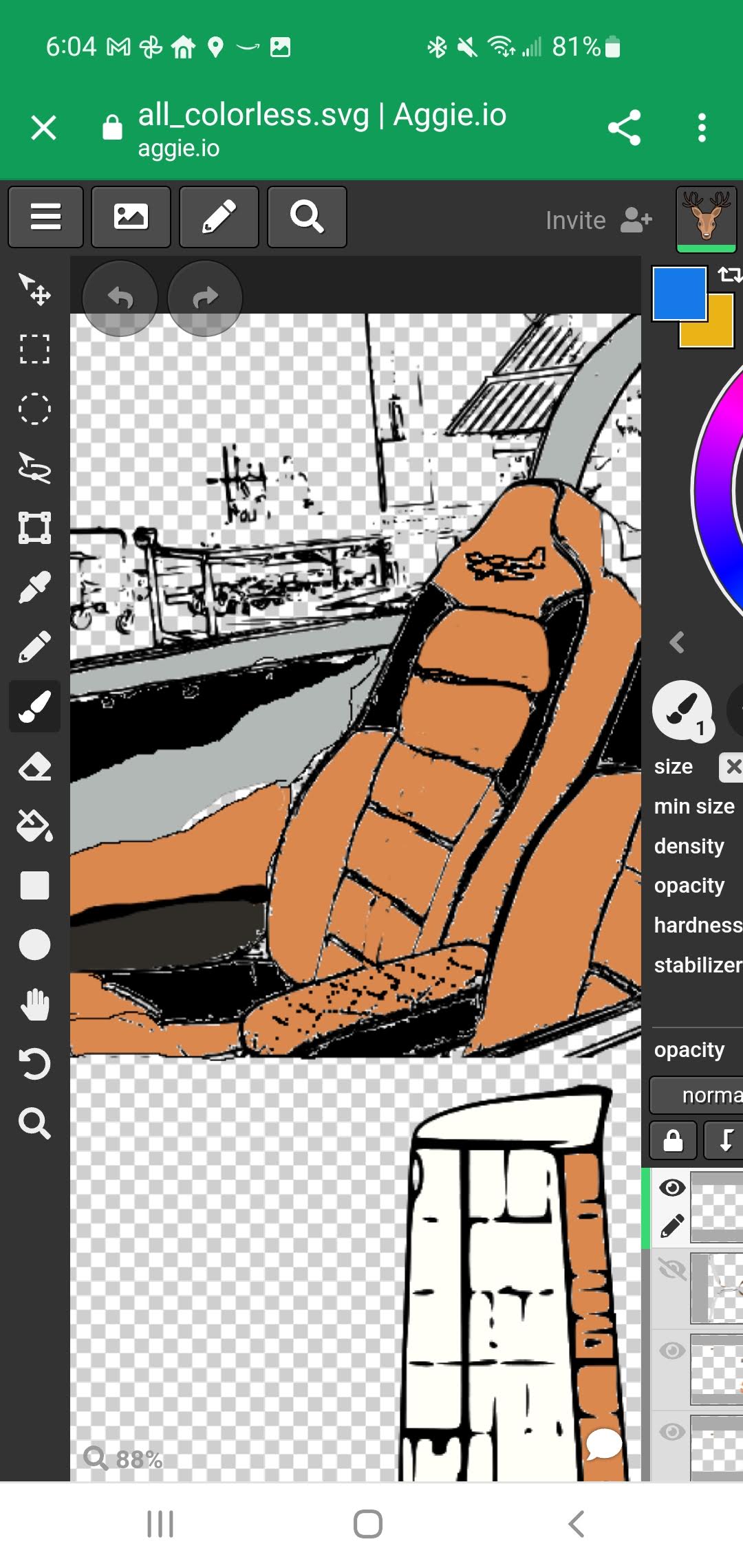
and in terms of materials (we would like to use ultraleather to be durable, stain-resistant, and animal-friendly). Sling Factory does not allow much customization, unfortunately, so we decided to go full send and sew our own upholstery. Stay tuned for the future blogposts to see how that turns out!
#fuselage #undercarriage #firewall-forward